Selamat datang kepada para pembaca blog saya.Disini saya ingin berkongsi ilmu tentang perkembangan teknologi masa kini yang patut para pembaca mengetahuinya..
Rabu, 5 Oktober 2011
Isnin, 19 September 2011
Ferrari F1


| Engine | |
| Configuration | Type 056 90º V8 |
| Location | Mid, longitudinally mounted |
| Weight | 95 kilo / 209.4 lbs |
| Construction | aluminium alloy block and head |
| Displacement | 2.398 liter / 146.3 cu in |
| Bore / Stroke | 98.0 mm (3.9 in) / 38.9 mm (1.5 in) |
| Valvetrain | 4 valves / cylinder, DOHC |
| Fuel feed | Fuel Injection |
| Aspiration | Naturally Aspirated |
| Red Line | 18000 rpm |
Keihin Carburetors
Rabu, 24 Ogos 2011
Selasa, 16 Ogos 2011
Cara soldering
4. Having completed soldering the circuit the extended legs on the components need to be trimmed using wire clippers. The circuit is now ready for testing.
Sabtu, 6 Ogos 2011
Fungsi Breadboards

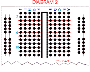
On the breadboard (diagram 1) seen opposite, letters are used to identify vertical columns and numbers to identify horizontal rows.

The red lines on diagram 2 show how some vertical columns and horizontal rows are internally connected. When power is applied to the breadboard current flows along these internal connections.

Khamis, 4 Ogos 2011
Bulb


L.E.D

 Light Emitting Diodes (LED) are very rugged, they last a very long time and they are an optical source. (A LIGHT SOURCE)
LEDs produce red, green, yellow, or orange light. They are used in a range of products

Infrared LEDs are also available although light from this type cannot be seen by the human eye. These are used in security devices.
LEDs are part of the diode family, consequently they must be connected the right way round or current will not pass through. They are usually protected by a resistor.
bateri sel kering

School projects are powered by batteries because they are safe, easily bought and safe.
Pembahagian voltage
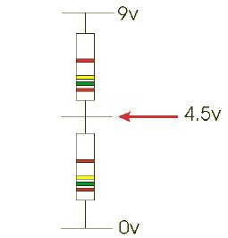
What are they - they can be used to split the voltage of a circuit. They are widely used in electronic circuits for setting and adjusting voltages - e.g. in radios, games and toys. You may find that you need a supply of 6 volts and you have a 9 volt battery, your only option may be to make a potential divider.

When two resistors of equal value (e.g. 1K) are connected across a supply, current will flow through them. If a meter is placed across the supply shown in the diagram it will register 9v. If the meter is then placed between the 0v and the middle of the two resistors it will read 4.5v. The battery voltage has been divided in half.

If the resistor values are changed to 2K and 1K the voltage will be 6v. The voltage at the centre is determined by the ratio of the two resistor values and is given by the formula:
V = supply voltage x R2/R1+R2
V= 9v x 2000 1000+2000 v = 9v x (2000/3000 ohms) V = 9v x 0.6666666 ohms V = 6v
Fungsi capacitor dalam litar

USING A CAPACITOR AS PART OF A 555 TIMER
Some of the components are resistors and capacitors. It is often the combination of resistors and capacitors that control the time delay - in this case the length the buzzer sounds for.
If the capacitor C1 is changed for a higher value capacitor then the buzzer sounds for a longer period of time. The variable resistor VR1 can also determine the length of time.
Rabu, 3 Ogos 2011
Capacitor

A capacitor (formerly known as condenser) is a device for storing electric charge. The forms of practical capacitors vary widely, but all contain at least two conductors separated by a non-conductor. Capacitors used as parts of electrical systems, for example, consist of metal foils separated by a layer of insulating film.
A capacitor is a passive electronic component consisting of a pair of conductors separated by a dielectric (insulator). When there is a potential difference (voltage) across the conductors, a static electric field develops across the dielectric, causing positive charge to collect on one plate and negative charge on the other plate. Energy is stored in the electrostatic field. An ideal capacitor is characterized by a single constant value, capacitance, measured in farads. This is the ratio of the electric charge on each conductor to the potential difference between them.
Capacitors are widely used in electronic circuits for blocking direct current while allowing alternating current to pass, in filter networks, for smoothing the output of power supplies, in the resonant circuits that tune radios to particular frequencies and for many other purposes.
A capacitor consists of two conductors separated by a non-conductive region.[8] The non-conductive region is called the dielectric or sometimes the dielectric medium. In simpler terms, the dielectric is just an electrical insulator. Examples of dielectric mediums are glass, air, paper, vacuum, and even a semiconductor depletion region chemically identical to the conductors. A capacitor is assumed to be self-contained and isolated, with no net electric charge and no influence from any external electric field. The conductors thus hold equal and opposite charges on their facing surfaces,[9] and the dielectric develops an electric field. In SI units, a capacitance of one farad means that one coulomb of charge on each conductor causes a voltage of one volt across the device
Networks
- For capacitors in parallel
- Capacitors in a parallel configuration each have the same applied voltage. Their capacitances add up. Charge is apportioned among them by size. Using the schematic diagram to visualize parallel plates, it is apparent that each capacitor contributes to the total surface area.
- For capacitors in series
- Connected in series, the schematic diagram reveals that the separation distance, not the plate area, adds up. The capacitors each store instantaneous charge build-up equal to that of every other capacitor in the series. The total voltage difference from end to end is apportioned to each capacitor according to the inverse of its capacitance. The entire series acts as a capacitor smaller than any of its components.
- Capacitors are combined in series to achieve a higher working voltage, for example for smoothing a high voltage power supply. The voltage ratings, which are based on plate separation, add up, if capacitance and leakage currents for each capacitor are identical. In such an application, on occasion series strings are connected in parallel, forming a matrix. The goal is to maximize the energy storage of the network without overloading any capacitor

SMD resistor
 SMD resistors
Surface mounted resistors are printed with numerical values in a code related to that used on axial resistors. Standard-tolerance surface-mount technology (SMT) resistors are marked with a three-digit code, in which the first two digits are the first two significant digits of the value and the third digit is the power of ten (the number of zeroes). For example:
| 334 | = 33 × 104 ohms = 330 kilohms |
| 222 | = 22 × 102 ohms = 2.2 kilohms |
| 473 | = 47 × 103 ohms = 47 kilohms |
| 105 | = 10 × 105 ohms = 1.0 megohm |
Resistances less than 100 ohms are written: 100, 220, 470. The final zero represents ten to the power zero, which is 1. For example:
| 100 | = 10 × 100 ohm = 10 ohms |
| 220 | = 22 × 100 ohm = 22 ohms |
Sometimes these values are marked as 10 or 22 to prevent a mistake.
Resistances less than 10 ohms have 'R' to indicate the position of the decimal point (radix point). For example:
| 4R7 | = 4.7 ohms |
| R300 | = 0.30 ohms |
| 0R22 | = 0.22 ohms |
| 0R01 | = 0.01 ohms |
Precision resistors are marked with a four-digit code, in which the first three digits are the significant figures and the fourth is the power of ten. For example:
| 1001 | = 100 × 101 ohms = 1.00 kilohm |
| 4992 | = 499 × 102 ohms = 49.9 kilohm |
| 1000 | = 100 × 100 ohm = 100 ohms |
000 and 0000 sometimes appear as values on surface-mount zero-ohm links, since these have (approximately) zero resistance.
More recent surface-mount resistors are too small, physically, to permit practical markings to be applied.
microfon
 A microphone, sometimes referred to as a mike or mic, is an acoustic to electric transducer that converts sound into an electrical signal. Microphones are used in many applications such as telephones, tape recorders, hearing aids, motion picture production, live and recorded audio engineering, in radio and television broadcasting and in computers for recording voice, VoIP. Several early inventors built primitive microphones prior to Alexander Bell, but the first commercially practical microphone was the carbon microphone conceived in October, 1876 by Thomas Edison.
Alat ukur
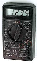
A DIGITAL Multimeter is highly accurate and easier to read than an analogue type. It is best used for finding the precise value of a voltage, current or resistance.
 An ANALOGUE Multimeter is less expensive and less precise than a digital type. Often it will be used for measuring a slowly changing voltage, current or resistance.


