Halaman

Sabtu, 6 Ogos 2011

Fungsi Breadboards


Breadboards are used to test circuits. Wires and components are simply pushed into the holes to form a completed circuit and power can be applied. One of the main advantages of using a breadboard is that the components are not soldered and if they are positioned incorrectly they can be moved easily to a new position on the board.
On the breadboard (diagram 1) seen opposite, letters are used to identify vertical columns and numbers to identify horizontal rows.
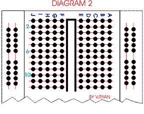


The red lines on diagram 2 show how some vertical columns and horizontal rows are internally connected. When power is applied to the breadboard current flows along these internal connections.
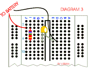


Diagram 3 shows how a 380 ohm resistor and an LED are setup on a breadboard. When a 9 volt battery is attached the LED lights. Try replacing the resistor with a higher value such as a 680 ohm resistor. The resistance will be greater and the LED should shine less bright.




Khamis, 4 Ogos 2011

Bulb


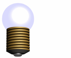
Bulbs have been used in electronics for along time and they are used in a wide range of circuits. Almost everyone has used a torch and if you look closely at the light source, it is more than likely that it is a bulb. In more recent years bulbs have been slowly replaced by LEDs as these are brighter, much more reliable, cheaper, energy efficient and have a much longer working life. They are also available in a range of colours. However, bulbs are still popular.

L.E.D

Light Emitting Diodes (LED) are very rugged, they last a very long time and they are an optical source. (A LIGHT SOURCE)
LEDs produce red, green, yellow, or orange light. They are used in a range of products

Infrared LEDs are also available although light from this type cannot be seen by the human eye. These are used in security devices.
LEDs are part of the diode family, consequently they must be connected the right way round or current will not pass through. They are usually protected by a resistor.


bateri sel kering


Batteries come in all shapes and sizes. They store electrical charge and as we all know when they are put into an electronic device such as a portable radio, they provide the power. The usual battery sizes are seen opposite. These are the type used in school projects and range from 1.5 volts to 9 volts.
School projects are powered by batteries because they are safe, easily bought and safe.


Pembahagian voltage


What are they - they can be used to split the voltage of a circuit. They are widely used in electronic circuits for setting and adjusting voltages - e.g. in radios, games and toys. You may find that you need a supply of 6 volts and you have a 9 volt battery, your only option may be to make a potential divider.


When two resistors of equal value (e.g. 1K) are connected across a supply, current will flow through them. If a meter is placed across the supply shown in the diagram it will register 9v. If the meter is then placed between the 0v and the middle of the two resistors it will read 4.5v. The battery voltage has been divided in half.

If the resistor values are changed to 2K and 1K the voltage will be 6v. The voltage at the centre is determined by the ratio of the two resistor values and is given by the formula:

V = supply voltage x R2/R1+R2

V= 9v x 2000

1000+2000

v = 9v x (2000/3000 ohms)

V = 9v x 0.6666666 ohms

V = 6v


Fungsi capacitor dalam litar


USING A CAPACITOR AS PART OF A 555 TIMER

The 555 circuit shown above is more sophisticated than the circuit above and is composed of several components included the integrated circuit (NE555). When switched on the buzzer sounds for a certain amount of time.
Some of the components are resistors and capacitors. It is often the combination of resistors and capacitors that control the time delay - in this case the length the buzzer sounds for.
If the capacitor C1 is changed for a higher value capacitor then the buzzer sounds for a longer period of time. The variable resistor VR1 can also determine the length of time.

Rabu, 3 Ogos 2011

Capacitor

A capacitor (formerly known as condenser) is a device for storing electric charge. The forms of practical capacitors vary widely, but all contain at least two conductors separated by a non-conductor. Capacitors used as parts of electrical systems, for example, consist of metal foils separated by a layer of insulating film.

A capacitor is a passive electronic component consisting of a pair of conductors separated by a dielectric (insulator). When there is a potential difference (voltage) across the conductors, a static electric field develops across the dielectric, causing positive charge to collect on one plate and negative charge on the other plate. Energy is stored in the electrostatic field. An ideal capacitor is characterized by a single constant value, capacitance, measured in farads. This is the ratio of the electric charge on each conductor to the potential difference between them.

Capacitors are widely used in electronic circuits for blocking direct current while allowing alternating current to pass, in filter networks, for smoothing the output of power supplies, in the resonant circuits that tune radios to particular frequencies and for many other purposes.


Charge separation in a parallel-plate capacitor causes an internal electric field. A dielectric (orange)
reduces the field and increases the capacitance.

A capacitor consists of two conductors separated by a non-conductive region.[8] The non-conductive region is called the dielectric or sometimes the dielectric medium. In simpler terms, the dielectric is just an electrical insulator. Examples of dielectric mediums are glass, air, paper, vacuum, and even a semiconductor depletion region chemically identical to the conductors. A capacitor is assumed to be self-contained and isolated, with no net electric charge and no influence from any external electric field. The conductors thus hold equal and opposite charges on their facing surfaces,[9] and the dielectric develops an electric field. In SI units, a capacitance of one farad means that one coulomb of charge on each conductor causes a voltage of one volt across the device


Several capacitors in parallel.

Networks

For capacitors in parallel
Capacitors in a parallel configuration each have the same applied voltage. Their capacitances add up. Charge is apportioned among them by size. Using the schematic diagram to visualize parallel plates, it is apparent that each capacitor contributes to the total surface area.
C_{eq}= C_1 + C_2 + \cdots + C_n
For capacitors in series
Several capacitors in series.
Connected in series, the schematic diagram reveals that the separation distance, not the plate area, adds up. The capacitors each store instantaneous charge build-up equal to that of every other capacitor in the series. The total voltage difference from end to end is apportioned to each capacitor according to the inverse of its capacitance. The entire series acts as a capacitor smaller than any of its components.
 \frac{1}{C_{eq}} = \frac{1}{C_1} + \frac{1}{C_2} + \cdots + \frac{1}{C_n}
Capacitors are combined in series to achieve a higher working voltage, for example for smoothing a high voltage power supply. The voltage ratings, which are based on plate separation, add up, if capacitance and leakage currents for each capacitor are identical. In such an application, on occasion series strings are connected in parallel, forming a matrix. The goal is to maximize the energy storage of the network without overloading any capacitor